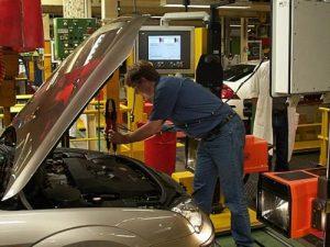
Headlamp Aiming and Calibration Systems
rpGatta has been the North American Sales, Integrator, and Service Representative for L.E.T. since the year 2000. L.E.T.’s core business is Headlamp Aiming and Final Line Calibration. Since 1967 L.E.T. has been developing state of the art sensors and technology to adapt to the fast changing automotive market needs for renowned car manufactures like Ford, Volkswagen, Daimler, Volvo, Renault, Toyota, BMW, Tesla, etc.
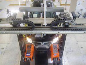
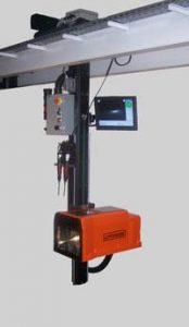
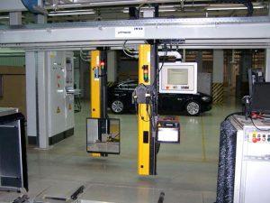
Headlamp and Foglamp Aiming System: the LUMINOSCOPE® LVC 2035 is a compact, digital headlight aiming system that can be used both for aiming and auditing the alignment of automotive headlamps.
It is based on the latest technology of image processing techniques by using an intelligent CMOS camera. The great advantage for the end user is that a PC is no longer required to operate the system. This enhances the reliability of the system and the costs of after service in comparison to PC operated audit systems. Communication with plant quality databases allows aiming or audit data to be tracked and automatically uploaded.
The algorithms allow setting of main, dipped, SAE and fog beams for LHD and RHD vehicles according to European, American, Asian and Chinese regulations.
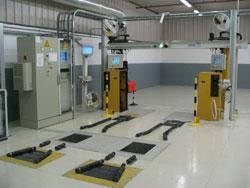
The system is equipped with a control panel, integrating an operator guiding system for positioning the machine in front of the headlamp. The electronic “Position Check” uses photocells around the lens to calculate and control the position of the LUMINOSCOPE® in front of the headlamp.
The criteria that define whether the headlamp is aimed correctly, are fully pre-settable so that the LUMINOSCOPE® LVC 2035 aiming system can be modified to the customer’s needs.
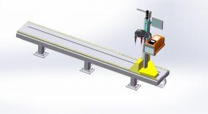
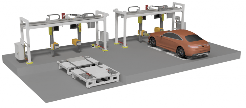
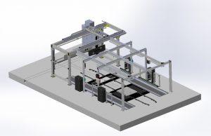
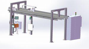
Automatic Positioning System Option: The LUMINOSCOPE® module for automatic movement and positioning.
Based on the selected vehicle, the LUMINOSCOPE® will move and sequentially position itself in front of the lamps that are programmed in the cycle that corresponds with the car.
The programming of the cycle of each car can be done easily by trained plant personnel.
Software is available for advanced settings such as speed at different levels, impact of track error, frequency of zeroing and many more features.
Automatic Screwdriver (C-DIS) Option: The LUMINOSCOPE® module for computer controlled adjustment of headlamps by electric screwdrivers. May be single or double screw drivers for reduced cycle time.
D.I.S. software offers smart screwdriver-control and parameters for optimal operation and speed.
Different types of headlights can be adjusted with different tools. The selections, once defined in the settings, come with the identification of the vehicle. Screwdrivers with LED lights can be provided for illumination of the aiming screw area in difficult dark conditions.
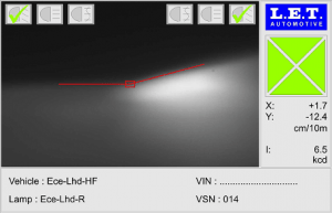
LCD Monitor Option: An additional 15″ LCD touch screen color display mounted on the moving mast shows a real time image and various easy to read messages
The camera image and measurement data are visualized together with a simulation of the cut-off line as calculated by the machine
This “real time” image of the headlamp pattern, together with indicating arrows that visualize in which direction the headlamp must be aimed, allow an easy and precise aiming of the headlamp by the operator
Other Recommended Options Include:
- Calibration and alignment laser that guarantees proper functioning and accurate aiming results
- Ticket Printer to log physical record of results (suitable for manually positioned audit systems)
Driver Assistance Calibration and Checking Systems
Our capabilities include:
- Driver Assistance Calibration and Checking Systems:
- Adaptive Cruise Control or Adaptive Distance Radar
- Blind Spot Detection
- Lane Departure Warning or Lane Change Assistance
- Rear View Camera
- Multipurpose Camera
- Night Vision Camera
- 360° Surround/Top View Cameras
- Error Proofing and Diagnostics for Vehicle Height and Position in Cell
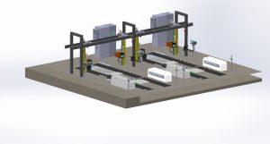
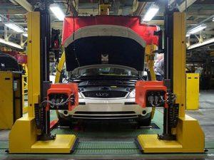
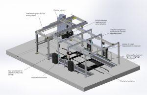
L.E.T. and rpGatta partner to offer complete Driver Assistance Calibration and Checking Systems. Driver Assistance Systems (DAS) are becoming more and more important in the modern car. We have become heavily involved developing reliable and accurate technology to adjust and calibrate radars, cameras, and other sensors. Often it is convenient to perform all calibration at the end of line during wheel alignment or as separate stand alone units. DAS calibration systems can be integrated into one cell including headlamp aiming and all other sensor calibration to reduce floor space and controls system costs. L.E.T. for many years has standard calibration systems that mount along side automatically positioned head lamp aiming gantries.
Radar and Lidar Sensor Calibration: Adaptive Cruise Control (ACC) or Adaptive Distance Radar (ADR) sensors measures the distance from and speed of the vehicle in front, and monitors / controls the speed and distance of the source vehicle. Blind spot detection and collision avoidance sensors are mounted at the back and sides of a car for detecting objects in the closer environment of the vehicle. As such, the driver can be warned if hidden objects may cause a collision or the vehicle may take action to correct the vehicles trajectory.
Our systems are able to used sensor feedback to calibrate radars and sensors by the use of a plate with corner reflectors, that is positioned in Y and Z direction. A later extension with an X movement is possible if required.
Multipurpose Camera Calibration: Lane Departure Warning, Lane Change Assistance, Blind Spot Detection, Rear View Cameras, Night Vision Cameras, and 360° Surround/Top View Cameras can all be calibrated by by positioning special targets, templates, reflectors, and special finished surfaces to calibrate sensors and cameras.
Vehicle alignment technology is able to determine the exact height and position of the vehicle regardless of wheel alignment systems accurately calibrate all sensors and provide advanced diagnostics.
Calibration is achieved by utilizing stationary or X, Y, Z dynamically positioned target plates with a special finishing for a correct level of reflection around the vehicle in the station.
360° Surround/Top View Cameras homogeneous illumination is achieved with homogeneous lighting integrated to unify brightness around the vehicle and calibration can be achieved regardless of extreme lighting conditions.
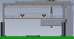
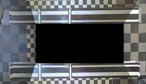
10m Wall

Description:
- The ‘intelligent’ 10m wall is a construction, made of aluminum profiles and two white panels with specific markings, for interpreting and estimation of the headlamp images and their adjustment
- The panels are motorized in Y/Z and can be remotely controlled
- A centrally integrated red laser can project a laser dot onto the headlamp of the vehicle in front to refer to the center or zero point of the lamp
- A number of photocells is horizontally positioned and integrated in the panels
- By moving the panels in both horizontal and vertical direction, a scan can be made of the headlamp image
- All measurement data of the light intensity is stored and used in the algorithm to calculate the gradient and the position of the cut-off line
- At the end of a cycle, the panel is positioning its reference line onto the calculated location of the cut-off line, to allow the operator to verify the result with his own visual interpretation
- The equipment is designed to be installed in a dark room with ambient light under 3 Lux
- A mechanical centralizer is required to position the vehicle in from the of the 10m Wall

